


Abstract
This article demonstrates a study on finite-time thermodynamic assessment and analysis of a Stirling heat engine. Finite-time thermodynamics is performed to specify the net thermal efficiency and power output of the Stirling system with finite-rate heat transfer, regenerative heat loss, conductive thermal bridging loss and finite regeneration process time. The model investigates effects of the inlet temperature of the heat source, the volumetric ratio of the engine, effectiveness of heat exchangers and heat capacitance rates on the net power output and thermal efficiency of the engine. Output power of the Stirling engine is maximized under two optimization scenarios. In the first scenario, the higher working temperature of the Stirling engine is considered as a decision design parameter (decision variable) while in the second scenario, in addition to the higher working temperature, the temperature ratio of the engine is also considered as a design parameter. Furthermore, the thermal efficiency of the cycle corresponding to the magnitude of the maximized power of the engine is evaluated. Finally, sensitivities of results towards shift in the thermal parameters of the engine are studied.
1 INTRODUCTION
Stirling cycle is one of the main original accepted air cycles for heat engines [1, 2]. Thanks to the gains of this cycle we can measure the proper efficiency and wide span of various fuels can be utilized for heating [2–4]. In recent studies [5, 6] it has been recognized that a Stirling engine has worthy capacity for compensating continuous power supplies in the range of 5–20 kW for water pumping requirements and electrical power generation throughout third world countries. The thermal efficiency of Stirling engines is 40% while the efficiency of similar Otto and Diesel engines are 25 and 35%, respectively. The Stirling engine cycle is a closed regenerative thermodynamic cycle, with cyclic expansion and compression of the working fluid at various temperatures [7–11]. Some important developments have been made in the framework of the novel division of irreversible thermodynamics, named thermodynamics with finite speed (TFS) [12–14]. The direct method developed in TFS [12–16] has been validated in 12 most performant Stirling engines in the world [12, 13, 17]. Based on this validation, a new scheme of computation of the performances (efficiency and power) of Solar Stirling engines have been established, which takes into account internal irreversibilities [12, 13, 18–21], in addition to the external irreversibilities taken into account in finite-time thermodynamic.
Meanwhile, finite-time thermodynamics [22–33] was performed for investigation of heat engines and outcomes, which are dissimilar from corresponding results obtained, executing the classical thermodynamics, have been achieved. The performance of the cycle is influenced visibly by finiteness of heat capacities of heat source and sink [34–38] as well as the heat leakage [39–42]. The optimum arrangement and the fundamental optimum performance of heat engines [35–38] with a finite time for the heat transfer at the heat source are different from similar results obtained using a time of heat transfer [43–45]. Furthermore, heat leakage alters the interrelationship between the optimal thermal efficiency and the power output [39–45]. Kaushik and Kumar [43, 44] illustrated a finite-time thermodynamic analysis of an endoreversible Stirling heat engine with internal heat loss in the regenerator and the finite heat capacity of the external reservoirs to maximize the power output and the conforming thermal efficiency.
The principle of operation of a solar thermal power plant is described by Lund [46], in terms of an internally reversible heat engine and finite heat transfer rates. In this regard, he presented some parametric equations. Ladas and Ibrahim [47] introduced a finite-time factor as the ratio of working fluid contact time to the engine time constant which develops the heat transfer features of the specified Stirling engine scheme. They accompanied a numerical investigation and depicted the shift in the power output against the finite-time factor, the variation in power output against efficiency. Furthermore, they studied the effects of the regeneration process on the thermal efficiency and output power. Smart model to predict Stirling heat engine power by execution of an evolutionary approach was performed by Ahmadi et al. [48–52]. Performance optimization of a linear phenomenological law system Stirling engine was studied by Chen [53]. Blank et al. [54] investigated the power optimization of an endoreversible Stirling cycle and afforded an estimation of possible performance for an actual engine.
In this paper, assuming that the duration of the regenerative process is proportional to the total time for isothermal progressions, we performed finite-time thermodynamic analysis. The finite-time thermodynamic model for simulation of the Stirling engine is developed with consideration about heat loss via conductive thermal bridge loss between heat sink and source and non-ideal behaviours of cold and hot heat exchangers. Hence expressions for net thermal efficiency and power output of the engine are gained. The net power output of the engine is maximized while the hot side the engine temperature is presumed as an optimization variable. Then the thermal efficiency of the cycle conforming to the maximized power is evaluated with substitution of the obtained optimal hot side temperature into the expression of thermal efficiency. Finally, the sensitivity of solutions and energy transfer values of the engine (including heat absorption, heat rejection, heat regeneration, thermal bridge loss and so on) is studied while engine parameters or operating conditions are changed. In this regard, effectiveness of cold and hot side heat exchangers, effectiveness of regenerator, inlet temperatures of cold and hot stream into the hot and cold side heat exchangers, compression and temperature ratios of the engine and conductive thermal bridge loss coefficient are involved as variables for sensitivity analysis.
2 SYSTEM DESCRIPTION
Figure 1 represents a graphical representation of a Stirling heat engine cycle with regenerative heat losses and finite-time heat transfer. As demonstrated in Figure 2, the Stirling cycle comprises four progressions. Process 1–2 is an isothermal progression, wherein the working fluid is compressed at a consistent temperature, Tc, and released heat to the heat sink at a low temperature, , thus, the heat sink temperature increases to Formerly the working fluid passes the regenerator and is heated up to Th throughout an isochoric progression 2–3. Throughout process 3–4, expansion of the working fluid occurs at a constant temperature Th course and gains heat from the heat source wherein its temperature is decreased from into Final progression (4–1) is an isochoric cooling process, where the regenerator absorbs heat from the working fluid.
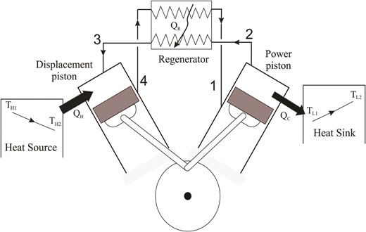
Schematic diagram of the Stirling heat engine cycle.
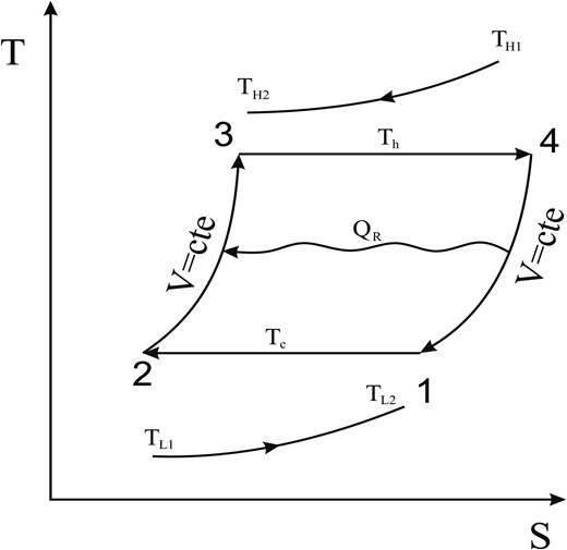
T–s diagram of the isothermal Stirling engine cycle.
Throughout an actual cycle it is unrealistic to have an ideal heat transfer within the regenerator wherein whole amount of gained heat (throughout the progression 4–1) is passed to the working fluid into the isochoric heating progression (progression 2–3). Consequently, a heat transfer loss represented by ΔQr has occurred throughout the regenerator. Moreover, a conductive heat transfer between the heat sink and the heat source, viz. as thermal bridge loss (Q0), is occurred.
3 THERMODYNAMICS ANALYSIS OF THE SYSTEM
In this section a thermal model based on the finite-time thermodynamic for simulation of the Stirling cycle is developed as discussed subsequently.
3.1 Regenerative heat losses in the regenerator
In the above equations, n is the molar mass of the working fluid, Cv the working fluid molar specific heat capacity at constant volume (J mol−1 K−1), εr the regenerator effectiveness, Tc and Th stand for the working fluid temperatures in the cold space and hot space (in K), respectively.
3.2 The amount of heat released by the heat source and absorbed by the heat sink
3.2.1 The cyclic period
3.3 The conductive thermal bridging losses from the heat source to heat sink
4 NUMERICAL RESULTS AND DISCUSSION
With the purpose of assessing the influence of the heat source working fluid inlet temperature , heat capacitance rates (CL,CH), the effectiveness of the regenerator (εr), effectiveness of the heat exchangers (εH, εL) and the heat leak coefficient (K0) on the powered Stirling heat engine system, the rest variables are kept consistent as x = 0.5, CH = CL = 125 W K−1, n = 1 mol, λ = 2, R = 4.3 J mol−1 K−1, Cv = 15 J mol−1 K−1εL = 0.8, εH = 0.8, εr = 0.9, .
Two scenarios for optimization are performed in this study. In the first scenario, optimization is carried out with the consideration of the maximum temperature of the Stirling engine, considered as a design parameter (decision variable). In this scenario, the maximized power of the Stirling engine and its resultant thermal efficiency are obtained using Equations (24) and (25), respectively. In the second scenario, two design parameters including the highest temperature (Th) and temperature ratio (x) of the Stirling engine are considered, simultaneously. In this scenario, optimization might be performed using conventional mathematical approach or any kind of metahuristic method such as the Genetic Algorithm or Particle swarm methods. In this case, as we have only two design parameters (Th and x), optimization can be performed easily via a graphical approach. Figure 3 illustrates the graphical approach with the intention of specification optimum values of design variables for having the maximized power of the Stirling engine. Figure 3a shows the output power of the Stirling cycle as a function of Th and x.
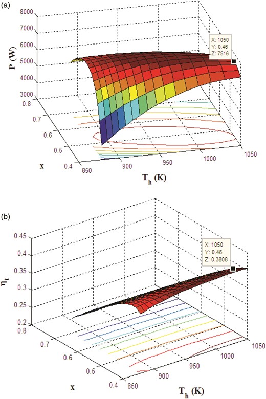
3D representation of (a) output power and (b) thermal efficiency of the Stirling engine in design parameters space including hot side temperature (Th) and x.
Similarly, Figure 3b illustrates the thermal efficiency of the engine as a function of Th and x.
Table 1 indicates the magnitude of the design parameter and the objective function as well as the corresponding thermal efficiency to the maximized output power for the proposed Stirling engine.
Values of design parameters and objective functions obtained in two optimization scenarios.
| Optimization scenario | xa | Th (K) | Tc (K)b | Pmax (W) | ηtc |
|---|---|---|---|---|---|
| Scenario 1: Only Th is considered as design parameter | 0.500 | 970 | 485 | 7927.4 | 0.385 |
| Scenario 2: Th and x is considered as design parameters | 0.460 | 1050 | 483 | 7516 | 0.381 |
| Optimization scenario | xa | Th (K) | Tc (K)b | Pmax (W) | ηtc |
|---|---|---|---|---|---|
| Scenario 1: Only Th is considered as design parameter | 0.500 | 970 | 485 | 7927.4 | 0.385 |
| Scenario 2: Th and x is considered as design parameters | 0.460 | 1050 | 483 | 7516 | 0.381 |
aIn the first scenario x is not considered as design parameter and it is kept constant (0.500).
bTc is not considered as design parameter. It is dependent parameter that can be obtained from design parameters including Th and x.
cThis thermal efficiency is corresponding thermal efficiency to the maximized power of the engine.
In the following section we survey the sensitivity of the maximized output power and its resultant thermal efficiency as well as other thermal performance of the engine, including work and heat transfer to the variation in the operating parameters of the engine. It is clear from Table 1 that in the case of the second scenario in which two design parameters are considered, the magnitude of the maximized output power (as objective function of this paper) and its corresponding thermal efficiency are, respectively, 1 and 1.5% higher than that of the first scenario.
4.1 Sensitivity of the engine performance to parameters of heat exchangers
4.1.1 Sensitivity to the effectiveness of the hot and cold heat exchangers (εL and εH)
Figure 4a and b illustrates the shift in the thermal efficiency of the proposed Stirling engine to the variation in the effectiveness of the hot side heat exchangers. Figure 4a illustrates this dependence at different effectiveness of the regenerator, while Figure 4b shows the same dependency at different inlet temperatures of the heat source fluid to the hot side heat exchanger.
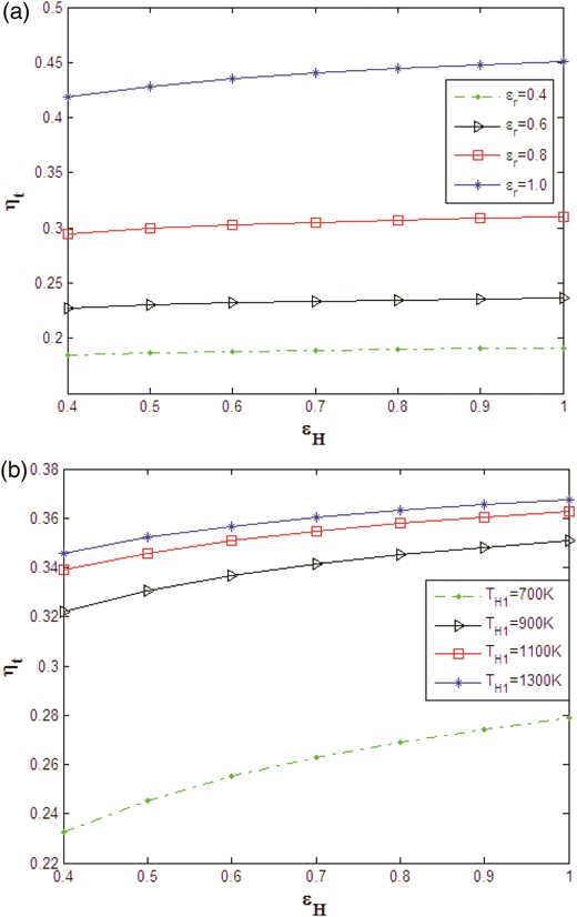
Variation of the thermal efficiency of the Stirling engine for different effectiveness of the hot side heat exchanger (a) at various effectiveness of the regenerator; (b) at various inlet temperature of the hot side heat exchanger.
These figures indicate that the thermal efficiency of the Stirling engine (corresponding to the maximized power output) increases as εH, εr and the inlet temperature of heat source fluid to the hot side heat exchanger, are increased. Comparison of Figure 4a and b indicates that the shift in the thermal efficiency to εH at various εr is minimum in comparison to dependence of the thermal efficiency to εH while is changed.
Similar trends are observed for the shift in the thermal efficiency of the proposed Stirling engine to the variation in the cold side heat exchangers' effectiveness, shown in Figure 5a and b. The figures indicate that the thermal efficiency increases as εL andεr are increased and the fluid inlet temperature at the cold side heat exchanger is decreased. Again more substantial dependence of the thermal efficiency to εL at various is observed in comparison to dependence of the thermal efficiency to εL at various εr.
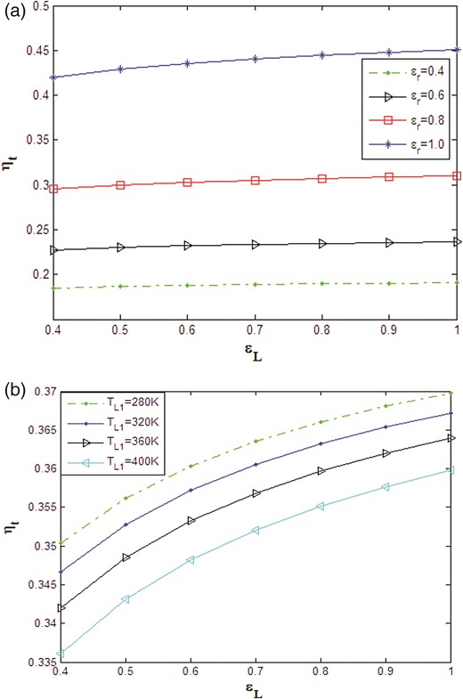
Variation of the thermal efficiency of the Stirling engine for different effectiveness of the cold side heat exchanger (a) at various effectiveness of the regenerator; (b) at various inlet temperature of the cold side heat exchanger.
Sensitivities of the maximized output power of the proposed Stirling engine to the hot and cold heat exchangers effectiveness at various effectiveness of the regenerator, various inlet temperature of hot fluid to the hot side heat exchanger and inlet temperature of the cold fluid to the cold side heat exchanger are illustrated in Figures 6a and b and 7a and b.
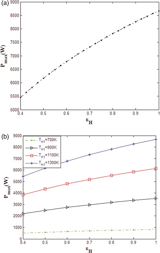
Variation of the maximum output power of the Stirling engine for different effectiveness of the hot side heat exchanger (a) at various effectiveness of the regenerator (curve is not dependent to εr); (b) at various inlet temperature of the hot side heat exchanger.
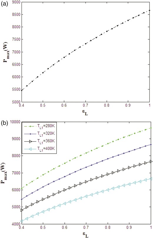
Variation of the maximum output power of the Stirling engine for different effectiveness of the cold side heat exchanger (a) at various effectiveness of the regenerator (curve is not dependent to εr) (b) at various inlet temperature of the cold side heat exchanger.
These figures show that the maximized power of the Stirling engine increases as εH, εL and are increased and is decreased. Figures 6a and 7a indicate no dependency of the maximized output power to the effectiveness of the regenerator. This fact is obvious from Equation (24) that is not dependent on the parameter of the regenerator.
4.1.2 Sensitivity to the inlet temperature of hot and cold fluid at the engine heat exchangers
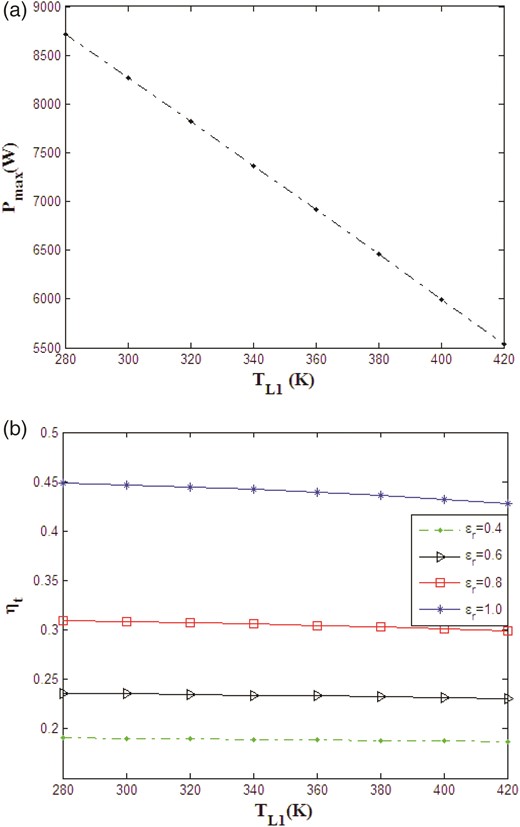
Figure 8a and b illustrates sensitivity of the maximized power and its resultant thermal efficiency to the inlet temperature of the hot fluid at the hot side heat exchanger, respectively. Figure 8a shows the leaner dependence of the maximized output power of the Stirling engine to . As expected, the maximized output power increases as is increased. Furthermore, it is clear that the maximized power has no sensitivity to the regenerator effectiveness as it is predicted by Equation (24). Figure 8b implies that the thermal efficiency of the Stirling engine (corresponding to the maximized power) is increased with and . Furthermore, this figure demonstrates that for all rising of the thermal efficiency is rapid for a temperature range starting from 700 K and then curves are flattened as is further increased. The temperature range where rapid increasing of the thermal efficiency is observed is wider at higher effectiveness of the regenerator. Out of this temperature range, curves are more flat for a lower. Moreover, it can be concluded from Figure 8b that dependence of the thermal efficiency to is more severe at higher values of .
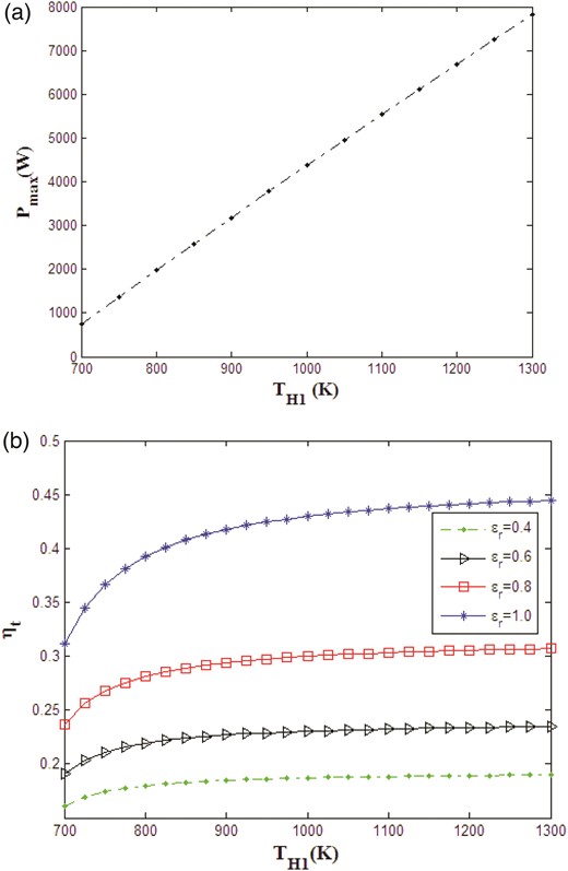
Effect of inlet temperature for the hot side heat exchanger on (a) maximum power output and (b) thermal efficiency of the Stirling engine.
Similar to Figure 8a and b, Figure 9a and b illustrates sensitivities of the maximized output power to the inlet temperature of the cold fluid at the cold side heat exchanger at various effectiveness of the cold side heat exchanger. The aforesaid figures imply that the maximized power and its resultant thermal efficiency of the engine increase as the regenerator effectiveness is improved or the inlet temperature of the cold side heat exchanger is reduced. Figure 9a indicates a leaner reduction in the maximized power with increasing in . Furthermore, Figure 9b indicates that the consequence of the regenerator effectiveness on thermal efficiency is more significant than the influence of on the thermal efficiency.
Effect of inlet temperature for the cold side heat exchanger on (a) maximum power output and (b) thermal efficiency of the Stirling engine.
4.1.3 Sensitivity to the heat capacitance rate of heat exchangers
Figures 10a, b as well as 11a and b indicate the shift in maximized power and the thermal efficiency of the Stirling cycle with a heat capacitance rate of the hot side heat exchanger at various hot fluid inlet temperatures and the hot side heat exchanger effectiveness, respectively. The mentioned figures illustrate that the maximized power and its conforming thermal efficiency of the engine are increased while the heat capacitance rate of the hot fluid at the hot heat exchanger, CH, as well as and εH increase. The increasing rate of these curves is more rapid at lower values of CH. Then the curves become flatten as the heat capacitance rate is increased further.
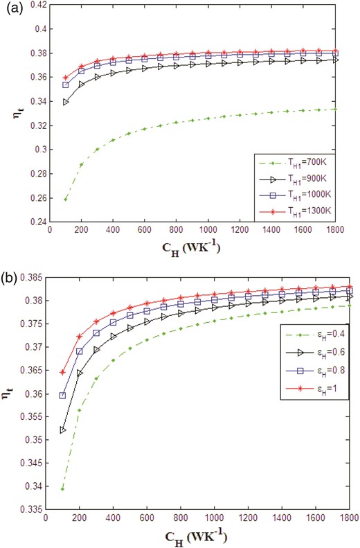
Variation of the thermal efficiency of the Stirling engine for different heat capacitance rate of the heat source at (a) various inlet temperature of the hot side heat exchanger (b) various effectiveness of the hot side heat exchanger.
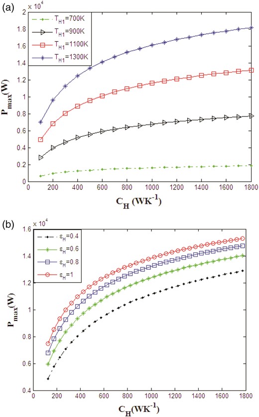
Variation of the output power of the Stirling engine for different heat capacitance rate of the heat source at (a) various inlet temperature of the hot side heat exchanger (b) various effectiveness of the hot side heat exchanger.
Similar trends as presented in Figures 10a, b as well as 11a and b are observed for the influence of the heat capacitance rate of the cold side heat exchanger at different cold fluid inlet temperature and the cold side heat exchanger effectiveness correspondingly in Figures 12a and b as well as 13a and b. It is obvious from the aforesaid figures that the maximized power and its parallel thermal efficiency increase while CL and εL are increased and the inlet the cold side heat exchanger temperature is decreased.
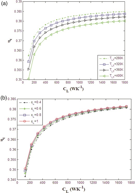
Variation of the thermal efficiency of the Stirling engine for different heat capacitance rate of the heat sink at (a) various inlet temperature of the cold side heat exchanger (b) various effectiveness of the cold side heat exchanger.
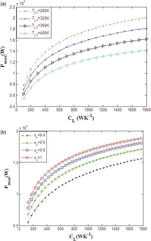
Variation of the output power of the Stirling engine for different heat capacitance rate of the heat sink at (a) various inlet temperature of the cold side heat exchanger (b) various effectiveness of the cold side heat exchanger.
4.2 Sensitivity of the engine performance to operating parameters of the engine
4.2.1 Sensitivity of the engine performance to the volumetric ratio of the engine (λ)
Figures 14a and b as well as 15a and b represent the effect of the engine volumetric ratio on the thermal efficiency and maximized power of the Stirling engine at different values for εr and, respectively. The maximized power of the Stirling engine and its analogous thermal efficiency increase while the volumetric ratio as well as εr and are increased.
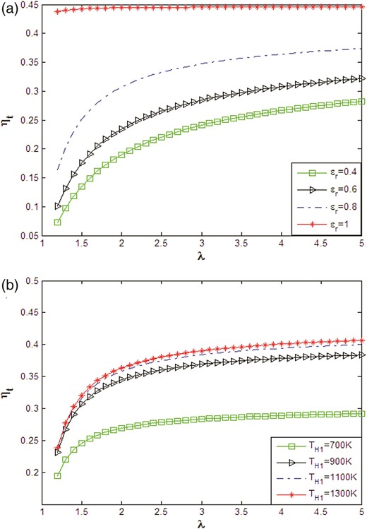
Variation of the thermal efficiency of the Stirling engine for different volumetric ratio (a) at various effectiveness of the regenerator (b) at various inlet temperature of the hot side heat exchanger.
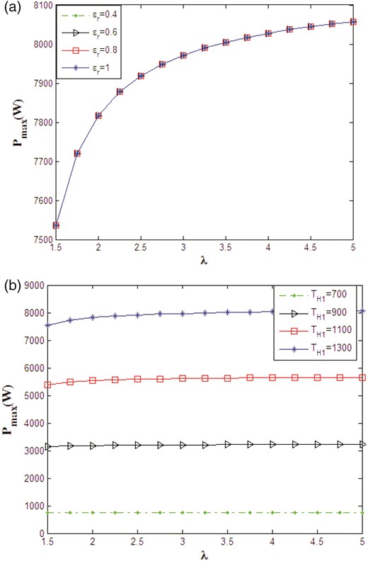
Variation of the maximum output power of the Stirling engine for different volumetric ratio (a) at various effectiveness of the regenerator (b) at various inlet temperature of the hot side heat exchanger.
4.2.2 Sensitivity of the engine performance to temperature ratio of the engine (x)
Figure 16 illustrates influence of the temperature ratio of the engine () on the thermal efficiency at different regenerator effectiveness. The aforementioned figure depicts a maximum for the thermal efficiency, which shows a shift towards higher values of x as the regenerative effectiveness increase. The reduction in the thermal efficiency after the peak is steepest for higher values of εr.
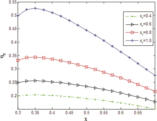
Variation of the thermal efficiency of the Stirling engine for different temperature ratio (x) at various effectiveness of the regenerator.
Similarly, Figure 17 illustrates the influence of the temperature ratio on the maximized power of the engine. It is found a peak around a value of x which was already obtained in Table 1 as optimum for x.
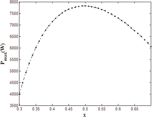
Variation of the output power of the Stirling engine for different temperature ratio (x) at various effectiveness of the regenerator.
4.2.3 Sensitivity of the engine performance to the conductive thermal bridge loss coefficient (K0)
Figure 18a–c indicates the consequence of the thermal bridge loss coefficient on the thermal efficiency of the engine at various , and εr. All figures imply that the thermal efficiency reduces, as expected, as the thermal bridge loss coefficient is improved. Figure 18a and b indicates that at a given value of K0, the reduction in the thermal efficiency is more significant for the lower values of and the higher values of . Figure 18c shows similar trends for the reduction in the thermal efficiency with increasing K0; however, at higher values of εr, the reduction is more steeper than that at the lower values.
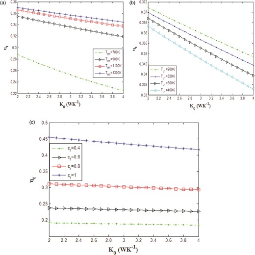
Variation of the thermal efficiency of the Stirling engine for different thermal bridge coefficient at (a) various inlet temperature of the hot side heat exchanger; (b) various inlet temperature of the cold side heat exchanger; (c) various effectiveness of the regenerator.
4.3 Effect of the system parameters on heat transfer and output work of the Stirling engine
In this section, the effect of all parameters discussed in previous sections (Sections 4.1 and 4.2) is assessed based on the magnitude of the output work (W) and heat transfer, including heat transfer in a regenerator and hot and cold heat exchangers denoted as Qr, QH and QL, respectively. Figure 19a–j presents the effect of , , εr, εH, CH, CL, λ, x and K0, respectively. Figure 19a and b shows that increase in and leads to increase in regeneration heat transfer and output work of the cycle. Figure 19a implies that the absorbed and rejected heats of the cycle have a minimum value at and increase when we have further increase in . In contrast, Figure 19b indicates an increase in the amount of the absorbed and rejected heats when increases.
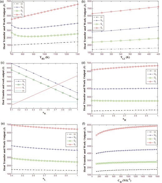
variation of heat transfers and output work of the Stirling engine with (a) inlet temperature of the hot side heat exchanger; (b) inlet temperature of the cold side heat exchanger; (c) effectiveness of the regenerator; (d) effectiveness of the hot side heat exchanger; (e) effectiveness of the cold side heat exchanger; (f) the heat capacitance rate of the heat source; (g) the heat capacitance rate of the heat sink; (h) volumetric ratio of the engine; (i) temperature ratio of the engine (x); (j) thermal bridge loss coefficient.
Figure 19c shows a linear reduction in amounts of absorbed and rejected heats and a linear increase in the regenerative heat when effectiveness of the regenerator increases. Furthermore, the figure implies that the output work does not vary, as expected, when effectiveness of the regenerator is changed. Figure 19d and e shows a minor effect of εH and εL on heat and work transfer of the engine. A minor increase in in Qr, QH and W is observed as shown in Figure 19d when εH is increased. The reduction in Qr, QH and QL is observed from Figure 19e as εL is reduced.
Figure 19f and g shows the increase in all parameters with an increase in CH and a decrease in all parameters with a decrease in CL.
Figure 19h shows a significant increase in the amount of output work, rejected heat and absorbed heat of the cycle when volumetric ratio of the engine is increased. The regeneration heat transfer is not dependent on the volumetric ratio as is shown from Figure 19h.
Figure 19j shows a reduction in all transfer parameters, including Qr, QH, QL and W, when the temperature ratio of the engine (x) is improved.
Finally, Figure 19j shows a minor increase in QH and QL when the thermal conductive bridge loss coefficient is improved. Here the work output and regeneration heat transfer almost remain constant.
5 CONCLUSIONS
Finite-time thermodynamics is used to determine the thermal efficiency of the powered Stirling heat engine and output power. Factors such as regenerative heat losses, finite-rate heat transfer, finite regeneration processes time and conductive thermal bridging losses are involved throughout the analysis. Further effects of the heat source/sink working fluid inlet temperatures and the heat capacitance rates as well as the efficiency of regenerator and heat exchangers were considered in evaluation of the thermal efficiency and output power of the engine executing Finite-time thermodynamic. The output power of the engine was maximized in two optimization scenarios in which the hot temperature and temperature ratio of the engine were considered as design parameters. Thermal efficiency of the cycle resembling to the maximized power is assessed. It was shown that in the second optimization scenario where two design parameters are considered, the magnitude of the thermal efficiency and maximized power were more than the corresponding values of the first scenario where only the hot temperature of the engine was taken as a design variable. Sensitivity of the maximized power and its parallel thermal efficiency to change in operating parameters and engine characterizing parameters were studied. It was shown that heat exchanger and regenerator parameters including effectiveness, thermal capacitance rate and fluid inlet temperatures as well as engine characterizing parameters including volumetric ratio, temperature ratio and thermal bridge coefficient have a significant effect on the maximized power and its analogous thermal efficiency, in one hand, and on work and heat transfer of the engine, on the other hand.
