


Abstract
OBJECTIVES: To characterize the remodelling effects and deformational forces of normosized rigid, semirigid and flexible mitral annuloplasty rings after implantation in healthy pigs.
METHODS: Measurements were performed in vivo with 80-kg porcine animals. Twenty-eight animals were randomized into a no ring group, a flexible ring group (Duran AnCore Ring, Medtronic, Minneapolis, MN, USA), a rigid ring group (Carpentier-Edwards Classic annuloplasty ring, Edwards Lifesciences, Irvine, CA, USA) and a semirigid ring group (Carpentier-Edwards Physio I annuloplasty ring, Edwards Lifesciences). Sonomicrometry crystals were implanted together with an annuloplasty ring and a dedicated mitral annular force transducer. The mitral annuloplasty rings were compared with respect to annular geometry and mitral annular forces.
RESULTS: Cyclic changes in the mitral annulus (MA) circumference were significantly lower for all ring groups (flexible: 7 ± 3 mm, semirigid: 4 ± 2 mm and rigid: 2 ± 1 mm) compared to the no ring group (11 ± 5 mm), implying the remodelling capacity of all annuloplasty rings. The cyclic change of the MA area and the septa-lateral and inter-commissural distances were equal in the semirigid and rigid ring groups and significantly lower compared to the no ring and flexible ring groups, suggesting a stronger and equal remodelling effect in the semirigid and rigid ring groups. Forces measured in the transducer reflected the remodelling capacity of the annuloplasty rings and were in general lower for the semirigid and rigid ring groups compared to the no ring and flexible ring groups. Especially the forces in the inter-commissural direction were significantly reduced for the semirigid and rigid ring groups (semi-rigid: 1.4 ± 0.8 N, rigid: 1.2 ± 0.8 N) compared to the no ring and flexible ring groups (no ring: 3.0 ± 1.1 N, flexible: 3.4 ± 1.6 N).
CONCLUSIONS: This study is the first to describe different remodelling effects and deformational forces of normosized mitral annuloplasty rings in vivo. Insights into the relationship between the remodelling effects and the accumulated forces of different mitral annuloplasty rings may have implications for ring selections in an aetiology-based mitral valve repair strategy. We propose the application of such a biomechanical approach for quantitative comparison of mitral annuloplasty rings and for future innovations on a rational basis.
INTRODUCTION
Surgical repair of the mitral valve (MV) is today the gold standard for treatment of mitral regurgitation and usually includes the implantation of an annuloplasty ring [1]. MV repair with mitral annuloplasty has proven to be a safe and durable method [2], associated with lower mortality rates and without postoperative use of anticoagulation therapy. Since the first introduction of a novel mitral annuloplasty ring in 1971 by Carpentier and colleges [3], the interest and research within this field have intensified. Improved imaging techniques have helped us to gain a better understanding of the sophisticated geometry of the MV apparatus [4] and contributed to the development of more physiological and flexible types of annuloplasty rings [5, 6].
Different MV diseases may require annuloplasty rings with different remodelling capacities. Several clinical studies have tried to compare the short- and long-term durability of annuloplasty rings with different degrees of rigidity used in either degenerative or ischaemic MV diseases. Although the rigidity of the annuloplasty ring is believed to impact the MV repair, these clinical studies have not been able to reach a confident conclusion [7]. Some studies have shown that the implantation of a flexible ring preserves the natural motion of the MV annulus compared to a rigid ring, although the clinical impact on the durability of the repair for degenerative valve disease has not been proved [8]. Despite the inability of the rigid rings to change shape, they have demonstrated superior durability compared to flexible rings in patients with ischaemic mitral regurgitation [9]. Mitral annuloplasty rings have also been described in several experimental studies comparing the native characteristics of the mitral annulus (MA) and the changes that occur when a clinically available mitral annuloplasty ring is implanted [10–14]. These studies were based on geometric parameters and differences in distance-derived strain distribution. It is reasonable to speculate that implantation of such differently designed annuloplasty rings may affect not only the geometry and dynamics but also heterogeneously affect the stress distribution of the MA and surrounding myocardial tissue and, thus, could in theory impair long-term durability. However, assessment tools for biomechanical characterization of different annular devices and repair strategies are still limited.
The aim of this in vivo study was to establish a biomechanical assessment tool to assess the remodelling effects of normosized rigid, semi-rigid and fully flexible mitral annuloplasty rings compared to the native mitral annulus (no ring). The remodelling effect following ring implantation was evaluated by combining measurements of annulus deformation and deformational forces using sonomicrometry tools and a dedicated mitral annular force transducer.
MATERIALS AND METHODS
Mitral annular force transducer and sonomicrometry
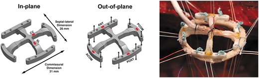
Mitral annular force transducer marked with outer dimensions and red markings for strain gauge positions for in-plane (left) and out-of-plane (middle) force measurements. The transducer was preattached to an annuloplasty ring with separate sutures prior to implantation (right). ANT: anterior; POST: posterior; ACOM: anterior commissure; PCOM: posterior commissure; SL: septal-lateral; CC: commissure to commissure.
The transducer was optimized to minimize the crosstalk by dividing the outer part of the transducer into 4 individual segments [15, 16]. Details about the development of the transducer, the calibration and the elimination of crosstalk between forces in plane and out of plane have been described previously [16].
In this study, the transducer was implanted together with different mitral annuloplasty rings attached between the transducer and the MA as shown in Fig. 1. By comparing the forces in different segments and directions with the measurement from the no ring group and the other ring groups, it was possible to compare the remodelling properties of different mitral annuloplasty rings. In the no ring group, the forces are directly transferred through the sutures attaching the transducer to the MA. In the ring groups, corresponding forces would be absorbed differently in the annuloplasty ring depending on the remodelling capacity on the MA.
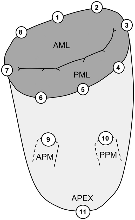
Location of implanted sonomicrometry crystals distributed around the mitral annulus and subvalvular apparatus. The positions of the crystals are defined from the anatomical landmarks: 1: centre of trigones; 2: right trigone; 3: posterior commissure; 4: P3 scallop; 5: centre of the posterior annulus (P2 scallop); 6: P1 scallop; 7: anterior commissure; 8: left trigone; 9: anterior papillary muscle (APM); 10: posterior papillary muscle (PPM); 11: left ventricular apex; AML: anterior mitral leaflet; PML: posterior mitral leaflet.
Experimental animal protocol
The measurements were performed in an 80-kg porcine model (Mixed Yorkshire and Danish Landrace pigs provided by University of Aarhus Experimental Animal Farm, Aarhus, Denmark). All animals were bred under standard laboratory conditions that complied with guidelines for experimental animal research and that were approved by the Danish Inspectorate of Animal Experimentation. The details about the experimental model were described previously [17]. Thirty-two animals were randomized into 4 groups: A no ring group, a flexible ring group (Duran AnCore Ring M31, Medtronic), a rigid ring group (Carpentier-Edwards Classic annuloplasty ring M32, Edwards Lifesciences, Irvine, CA, USA) and a semirigid ring group (Carpentier-Edwards Physio I annuloplasty ring M32, Edwards Lifesciences). Four animals could not be weaned from cardiopulmonary bypass and were excluded (2 each from the no ring and the rigid ring groups). The remaining 28 animals were evenly distributed with 7 animals in each group. The annuloplasty rings were normosized to the anatomical area of the anterior leaflet and corresponded to the MA area in systole.
Following cardiopulmonary bypass and cardioplegic arrest, 11 sonomicrometry crystals were implanted (Fig. 2). Before each experiment, the force transducer was attached to the annuloplasty ring using 8 non-compliant Ethibond braided sutures. The fixation of the transducer and annuloplasty ring is crucial to ensure a complete force transmission between ring and transducer; otherwise, the annular forces will appear lower due to absorption in the ring and consequently will not be transferred to the transducer. The force transducer and ring were then implanted through a left atriotomy (Fig. 1, right) using the same sutures that were used for the sonomicrometry crystals in the MA. For the no ring group, the transducer was implanted in a similar way, only without the annuloplasty ring. The area of the inner transducer arms was only 1.4 cm2 and since the diastolic in-flow is relatively non-turbulent, we assumed that the transducer location did not affect the haemodynamics during force measurements. Wires from the transducer and sonomicrometry crystals were exteriorized through the left atrium, and microtip pressure catheters were placed in the left ventricle and left atrium.
After the surgical procedure, the animals were weaned from cardiopulmonary bypass, and force and haemodynamic measurements were acquired. All animals received 0.5 mg CaCl prior to weaning from bypass. The inotropic effect of CaCl is only temporary, and CaCl is administered once to support the porcine heart in its critical phase. The force transducer was then removed from the beating heart by cutting the sutures through an atriotomy between the ring and the transducer, leaving only the sonomicrometry crystals in the MA. The geometric and haemodynamic measurements were then acquired in a second collection of data. The MV function was examined with 2D echocardiography at baseline, with and without the transducer, to confirm a competent valve function. After the measurements, the pigs were euthanized under continued anaesthesia with intravenous injection of pentobarbital. The hearts were explanted after the experiment to verify the positions of the sonomicrometry crystals.
Data acquisition
Strain signals from the mitral annular force transducer were acquired with data acquisition hardware (cDAQ model 9172 and NI-9237, National Instruments, Austin, TX, USA). Left ventricular and left atrial pressures were measured with microtip pressure catheters (SPR-350S, Millar Instruments, Houston, TX, USA) and amplified with a 2-channel pressure control unit (PCU-2000, Millar Instruments). An electrocardiogram (ECG) was obtained with a CardioMed system (Model 4008, CardioMed A/S, Oslo, Norway). Analogue signals from the pressure and ECG systems were acquired with data acquisition hardware (NI-9215, National Instruments). All strain and analogue data signals were recorded with dedicated virtual instrumentation software (LabVIEW 11.0, National Instruments). The signals from each sonomicrometry crystal were connected to a dedicated external ultrasound transceiver unit, and intercrystal distances were recorded with dedicated software provided by Sonometrics.
Data analysis
All force and geometric and hemodynamic data were recorded and analysed with dedicated virtual instrumentation software (LabVIEW 11.0, National Instruments). The time derivative of the left ventricular pressure (LV dP/dt) was used for synchronization between data acquired with LabVIEW and sonomicrometry software. Four time points were defined throughout each heart cycle: Mid-systole was defined as the midpoint between LV dP/dt maximum and minimum. End-diastole was defined as the R peak in the ECG, and end-systole was defined as the LV dP/dt minimum. Mid-diastole was defined as the midpoint between end-systole and the following LV dP/dt maximum.
Deformational forces were reported as the amplitude differences between the maximum and minimum values. Out-of-plane forces were calculated directly from the calibration, and in-plane forces were processed with the crosstalk elimination algorithm as previously described [16].
Intercrystal distances from sonomicrometry were post processed using a multidimensional scaling technique to represent each crystal in a Cartesian coordinate system (SonoSOFT and SonoXYZ, Sonometrics Corp.). The mitral annular area was calculated by projecting the annular crystals onto a least-square fit plane defined from the 8 annular crystals. A middle point of the crystals was defined on the least-square fit plane, and 8 triangles were defined by the middle point and 2 neighbouring annular crystals. The mitral annular area was then calculated as the summarized area of the 8 triangles. The mitral annular circumference was calculated as the summarized distance between the 8 annular crystals and was further divided into 8 segments calculated as the distance between 2 adjacent annular crystals. The short- and long axes of the MA were represented as the septal-lateral (SL) distance (crystals 1–5) and the commissure-commissure (CC) distance (crystals 3–7). All geometric parameters were reported with the maximum and minimum values, and the cyclic difference was calculated as the difference between the maximum and minimum values.
Excluded data
Due to technical difficulties with the force transducer, data from 5 single-strain gauges in 5 different animals were excluded (2 in both the rigid and semirigid ring groups and 1 in the no ring group). Also, geometric data were excluded from one of the animals with the rigid ring due to insufficient sonomicrometry signals.
Statistical analysis
Forces and geometric and hemodynamic data were acquired for 20 s for postoperative offline analysis and reported as an average of 10 consecutive heart cycles with a mean value ± standard deviation. Data from all the ring groups were analysed by two-way repeated measures ANOVA using group and repetitive heart cycles as factors. The model allowed for different residual variations in the groups. In the validation step, an inspection of the residuals and fitted values did not give cause to doubt this model. Groups were then compared using post hoc Wald z tests. Haemodynamic parameters were compared between groups using a one-way ANOVA followed by a Bonferroni post-hoc test. All data were analysed with STATA (StataCorp LP, College Station, TX, USA) and the significance level was defined as P < 0.05.
RESULTS
The haemodynamic data, shown in Table 1, indicate that there were no significant differences in heart rate, left ventricular pressure and LV dP/dt between groups. The heart rate and left ventricular pressure were slightly lower for the semi-rigid ring group, although non-significant. Therefore, we did not anticipate that the differences were caused by the ring type.
Haemodynamics of the ring groups (parameters measured with the force transducer)
| Groups | No ring | Flexible ring | Semi-rigid ring | Rigid ring | P* |
|---|---|---|---|---|---|
| HR, min−1 | 120 ± 25 | 111 ± 30 | 88 ± 31 | 124 ± 19 | 0.11 |
| LVPmax, mmHg | 107 ± 25 | 105 ± 28 | 95 ± 23 | 104 ± 20 | 0.80 |
| LV dP/dt, mmHg/s | 1767 ± 501 | 2272 ± 547 | 1708 ± 937 | 2202 ± 565 | 0.43 |
| Cross-clamp, min | 64 ± 25 | 66 ± 25 | 62 ± 32 | 74 ± 38 | 0.95 |
Mean ± standard deviation. HR: heart rate; LVPmax: peak left ventricular pressure; LV dP/dt: peak of left ventricular pressure change.
No significant difference between groups.
Mitral annular forces
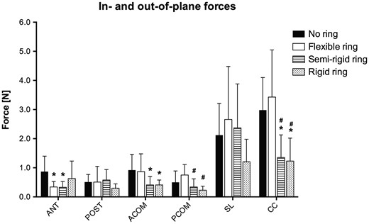
Forces measured in each group for the out-of-plane segments and in-plane directions. These forces represent the amount of force transferred from the mitral annulus and through the annuloplasty ring to the transducer on top. Hence a low force compared to the no ring group represents an accumulation of force within the ring itself. ANT: anterior; POST: posterior; ACOM: anterior commissure; PCOM: posterior commissure; SL: septal-lateral; CC: commissure to commissure. *: Different from the no ring group; #: Different from the flexible ring group. P < 0.05.
Mitral annulus deformational forces in different ring groups
| Out-of-plane segments, N | In-plane directions, N | |||||
|---|---|---|---|---|---|---|
| Groups | ANT | POST | ACOM | PCOM | SL | CC |
| No ring | 0.87 ± 0.53 | 0.51 ± 0.26 | 0.92 ± 0.54 | 0.50 ± 0.39 | 2.12 ± 1.09 | 2.98 ± 1.12 |
| Flexible ring | 0.34 ± 0.19a | 0.51 ± 0.54 | 0.87 ± 0.61 | 0.75 ± 0.36 | 2.66 ± 1.82 | 3.43 ± 1.62 |
| a: 0.031 | ||||||
| Semi-rigid ring | 0.33 ± 0.20a | 0.58 ± 0.36 | 0.41 ± 0.29a | 0.34 ± 0.28b | 2.37 ± 1.51 | 1.35 ± 0.78a,b |
| a: 0.037 | a: 0.045 | b: 0.023 | a: 0.024 | |||
| b: 0.003 | ||||||
| Rigid ring | 0.63 ± 0.60 | 0.30 ± 0.15 | 0.41 ± 0.17a | 0.23 ± 0.14b | 1.21 ± 0.77 | 1.23 ± 0.79a,b |
| a: 0.042 | b: 0.006 | a: 0.015 | ||||
| b: 0.002 | ||||||
Mean ± standard deviation. ANT: anterior; POST: posterior; ACOM: anterior commissure; PCOM: posterior commissure. SL: septal-lateral; CC: commissure-commissure.
Different from no ring group.
Different from flexible ring group.
Mitral annular geometry
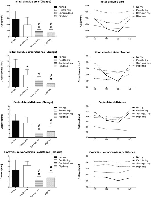
Mitral annulus deformation for each ring group. Left column illustrates the cyclic changes of selected variables in each group. Right column illustrates the absolute values for the same variables at 4 defined time points throughout the cardiac cycle. ED: end-diastole; MS: mid-systole; ES: end-systole; MD: mid-diastole. *: Different from the no ring group, #: Different from the flexible ring group. P < 0.05.
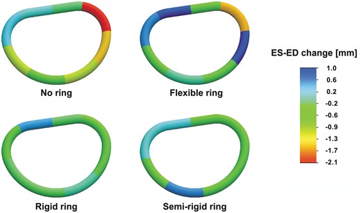
Segmental mitral annular circumferential changes from end-diastole to end-systole for the no ring group and the three annuloplasty ring groups. The annular circumferential changes are illustrated with a scaled colour legend where blue represents a systolic annular circumferential expansion and red represents a systolic annular compression. ES: end-systole; ED: end-diastole.
Mitral annulus geometry and cyclic deformation in different ring groups
| No ring | Flexible ring | Semi-rigid ring | Rigid ring | |||||||||
|---|---|---|---|---|---|---|---|---|---|---|---|---|
| Parameter | Max | Min | Change | Max | Min | Change | Max | Min | Change | Max | Min | Change |
| MAA, mm2 | 760 ± 106 | 612 ± 106 | 146 ± 61 | 756 ± 140 | 658 ± 153 | 98 ± 59 | 783 ± 93 | 739 ± 90 | 44 ± 16a,b | 684 ± 93 | 645 ± 85 | 40 ± 20a,b |
| a: <0.001 | a: <0.001 | |||||||||||
| b: 0.034 | b: 0.029 | |||||||||||
| MAC, mm | 112 ± 13 | 100 ± 15 | 11 ± 5 | 107 ± 9 | 100 ± 10 | 7 ± 3a | 107 ± 6 | 104 ± 5 | 4 ± 2a | 107 ± 6 | 105 ± 6 | 2 ± 1a,b |
| a: 0.011 | a: <0.001 | a: <0.001 | ||||||||||
| b: 0.021 | ||||||||||||
| SL distance, mm | 33.3 ± 1.6 | 29.1 ± 2.6 | 4.3 ± 1.7 | 33.0 ± 3.4 | 29.3 ± 4.1 | 3.7 ± 1.5 | 31.3 ± 1.7 | 30.3 ± 1.5 | 1.1 ± 0.3a,b | 29.5 ± 4.3a,b | 28.0 ± 5.4 | 1.5 ± 1.4a,b |
| a: <0.001 | a: 0.025 | a: 0.001 | ||||||||||
| b: <0.001 | b: 0.037 | b: 0.005 | ||||||||||
| CC distance, mm | 30.4 ± 3.4 | 27.1 ± 2.7 | 3.3 ± 2.0 | 34.7 ± 3.5a | 30.5 ± 3.9 | 4.2 ± 0.8 | 34.8 ± 3.0a | 33.4 ± 2.7a | 1.4 ± 0.7a,b | 32.0 ± 5.1 | 30.2 ± 4.8 | 1.8 ± 1.0a,b |
| a: 0.046 | a: 0.040 | a: 0.002 | a: 0.007 | a: 0.045 | ||||||||
| b: <0.001 | b: 0.001 | |||||||||||
Mean ± standard deviation. MAA: mitral annular area; MAC: mitral annular circumference; SL: septal-lateral (crystals 1–5); CC: commissure-commissure (crystals 3–7).
Different from no ring group.
Different from flexible ring group.
DISCUSSION
The native mitral annulus (no ring), we applied a biomechanical assessment tool to quantitate remodelling differences between rigid, semi-rigid and flexible mitral annuloplasty rings compared to the native mitral annulus (no ring). The biomechanical measurements were successfully performed with a dedicated mitral annular force transducer and sonomicrometry crystals to measure the ring characteristic following implantation. It is the first study to demonstrate significant differences in remodelling characteristics of annuloplasty rings based on a combination of geometric and force measurements.
The heterogeneous deformation of the MA (Fig. 5) with anterior dilatation and posterior contraction is consistent with the results from other studies [12]. The segmental annular deformation analysis of the native MV also correlates well with a recent study that measures suture forces at 10 separate locations around the annulus [18]. Although the suture forces do not include the distinction between dilatation and compression, the amplitudes correspond well to our data, with increased annular activity especially in the posterior commissural region. Our measurements also showed that the implantation of a rigid or semi-rigid ring with remodelling properties removes the freedom of annular movement and thereby increases the risk of increased suture forces and ring dehiscence.
The regional annular deformations in each annuloplasty ring group varied characteristically from those in the no ring group (Fig. 5). The flexible ring group showed both dilatation and compression in the posterior segment. Although the solid parts of the rigid ring were completely unbendable, the small opening in the anterior part might allow for some motion in that segment, which may also explain the observed higher force in the anterior segment compared to that in the semirigid ring (Fig. 3). The semi-rigid ring allowed minor deformation of the anterior part and completely fixated the posterior commissural part equally to the rigid ring.
The absolute values of the CC distances seem to be somewhat larger for all ring groups, but especially so for the semi-rigid ring group (Fig. 4, right column). This observation may be partially explained by differences in the true dimensions of the ring [19], although we used the same ring sizeM32 (M31 for the flexible ring). Furthermore, the size of each crystal was 2 mm, and, since they were placed on the atrial side between the annulus and the ring, the absolute dimensions may also be overestimated in some animals because the crystals were positioned just outside the ring.
All annuloplasty rings restricted cyclic mitral annular motion compared to the native MA (Fig. 4). The cyclic MA deformation and deformational forces were significantly different for the rigid and semi-rigid ring groups, which was indicative of a stronger remodelling effect. The observed different remodelling effects of flexible versus semi-rigid and rigid rings on the dynamics of the native MA were supported by previous findings in sheep [12, 14]. In relation to these results, it is relevant to consider whether the outcome would be different with a different ring size and how the results may be applicable to a downsized MA. Bothe and colleagues introduced the terms cardiac cyclic strain and ring strain [14] to distinguish changes in remodelling and downsizing, respectively. We hypothesized that the remodelling capacity of each ring described with the cyclic strain (same as ‘Change’ in Fig. 4) may be similar with a moderate degree of downsizing. In contrast, the ring strain or initial preconstraining of the MA due to downsizing depends on the ring size chosen. Introduction of ring strain (downsizing) may be intended, e.g. in cases with severe annular dilatation. but the overall remodelling capacity of the rings might be the same as in this study with normal-sized rings.
The range of in- and out-of-plane forces in the no ring group was comparable with values reported in similar studies [15, 20], although an exact comparison of the forces would be impossible due to principal differences in transducer design, calibration and experimental setup. Previous studies have indicated that the mitral annular dynamics are preserved with a flexible annuloplasty ring [11, 14], meaning that the remodelling capacity is low. In this study, the measured deformational forces of the flexible ring and native annulus were equal except for the anterior segment, indicating that almost no forces were accumulated in the normosized flexible ring. In contrast, the forces measured in the rigid and semi-rigid ring groups in general were significantly lower, meaning that some of the forces were accumulated in the ring itself and in the attachment sutures as a reflection of a higher degree of remodelling capacity. This effect was most prominent in the commissural segments and CC direction and for the rigid ring in the SL direction. Higher accumulated forces at the point of attachment of the rigid and semi-rigid rings are indicative of a stronger remodelling capacity that may obviously be intentional for MV repair. One may be aware that the accumulated forces are also distributed to the attachment sutures and may predispose to suture detachment [18, 21].
The force accumulation in the SL direction tended to be less in the semi-rigid than in the rigid ring group, which may reflect a more physiological adaptation of the MA in this direction as intended by the design of the Physio ring.
Limitations
The animals included in this study were healthy and nonischaemic. We investigated the remodelling effects of different mitral annuloplasty rings, but our results could be different if the rings are implanted in hearts with various LV ischaemic issues or MV diseases. Because this study only included non-diseased animals, we may only speculate what the outcome would have been with, for instance, a dilated MA. But we hypothesize that the generation of force and therefore the risk of dehiscence would be increased with the presence of an undersized remodelling annuloplasty ring. Furthermore, the long-term impact of different annuloplasty rings may not be revealed in a short-term study like this one. We know from experience that it is hard to reproduce a diseased pig model with the same degree of disease from pig to pig; therefore, we chose to use non-diseased pigs. Sizing of mitral annuloplasty rings is an essential part of a successful MV reconstruction. Although we used animals of the same race, gender and weight, minor size differences of the MV s are unavoidable.
The different annuloplasty ring groups (rigid, semi-rigid and flexible) were chosen because they are all widely used and often referred to in the literature. However, it is important to note that our results may be different for another aetiology-specific ring that is referred to as an e.g. rigid ring.
CONCLUSION
This study is the first to describe significant differences in annular geometric and deformational forces between normosized rigid, semi-rigid and flexible rings compared to the native heart (no ring). Therefore, it is a more comprehensive technique for measuring the remodelling capacity of different annuloplasty rings. We found no overall differences between the no ring and the flexible ring groups in terms of annular dynamics and force distribution, indicating only a limited remodelling capacity. The rigid and semi-rigid ring groups restricted the mitral annular dynamics equally, with no overall differences in remodelling capacity. Results from this study indicate that annuloplasty rings should be differentiated in terms of their actual remodelling capacity for ring selections in an aetiology-based MV repair strategy.
This study represents a step towards a more evidence-based approach to annuloplasty ring selection for reconstructive MV surgery. We propose the application of this biomechanical assessment tool for quantitative discrimination of commercially available annuloplasty rings. Furthermore, it may provide a rational platform for innovation and standardized validation of novel annuloplasty ring concepts that address disease-specific MV conditions.
Funding
This work was supported by the Danish Heart Foundation Grant #14-R97-A5166-22830, the Karen Elise Jensens Fond, the Arvid Nilssons Fond, the Aase og Ejnar Danielsens Fond, the Knud og Edith Eriksens Mindefond, the Raimond og Dagmar Ringgård-Bohns Fond, the Snedkermester Sophus Jacobsen & Hustru Astrid Jacobsens Fond, the Helga og Peter Kornings Fond and the Oticon Fonden.
Conflict of interest: none declared.
REFERENCES
Author notes
†Presented at the 29th Annual Meeting of the European Association for Cardio-Thoracic Surgery, Amsterdam, Netherlands, 3–7 October 2015.
